An A-SID trip, part 1
Posted by Stefano on Mon, 04 Jul 2022 14:19:01 GMT.

I've been playing with the C64 ever since I have memory. I probably even learnt to read and write on it. Yet I haven't asked myself how it generated sound until a few years ago, when I accidentally stumbled upon the MIDIbox SID. Since I do the work that I do, I looked around for information on the SID chip as well as on classic game music composers (such as the genius named Tim Follin) and modern chiptune music acts (YMCK are amazing). As I found out that:
- the SID chip contains a digitally-controlled resonant analog filter which can take analog audio as input;
- analog audio input and output are actually accessible through the A/V port on the back of the C64;
- people went as far as decapping the chip and taking die shots using light microscopes at micrometer resolution, and then reverse engineering the schematics from such pics;
I knew that one day or another I had to do something about it. And here we are now. Let me tell you about the long journey towards the creation of A-SID and its release on 2022-06-04. (should we call it C64 day now?)
A first BASIC prototype
As I haven't written a line of C64 code for decades, I wanted to first get a feel for what the computational power of the machine was like. The quickest way to do that was to fire up VICE and spit out some good old BASIC. After a couple of days worth of programming I got to have the following thing working.
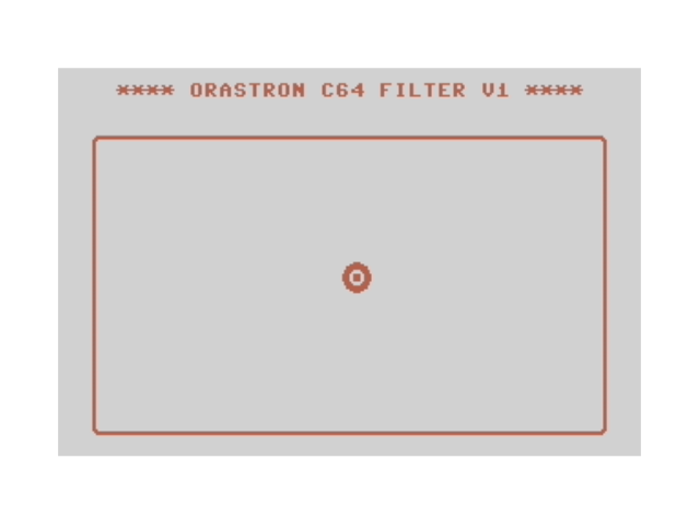
Essentially, this program generates a filtered fixed-frequency sawtooth wave and you control the cutoff and resonance of the filter by moving the target on the screen (cutoff is on the x-axis and resonance on the y-axis) via the joystick in port 1.
There's nothing particularly exciting about this little piece of code: the UI is just a bunch of text printed on the screen at boot in Standard Character Mode and the target, which is the only moving part, is a sprite. The SID chip is initialized at the beginning of execution and a main loop reads the joystick, calculates the next target position, and triggers a routine that actually moves the sprite on screen and updates SID registers.
This required only about 60 lines of BASIC code (compare that to modern software...) but it's so slow to use it hurts. My conclusion was that programming the SID is quite easy but there's no way anything fun can be developed in pure BASIC. Plus, I had no idea how much slower BASIC is compared to machine code, so I just decided that any further development would squeeze as much performance out of the machine as I would be able to.
Anyway, in case you find it interesting, here's the source code:
1 poke 53280,1: poke 53281,15:      rem set background color
2 poke 646,2:                       rem set text color
3 print chr$(147):                  rem clear screen
4 print "    **** orastron c64 filter v1 ****"
5 mx = 0: my = 4: gosub 1000: rem move to 3,7
6 print "  UCCCCCCCCCCCCCCCCCCCCCCCCCCCCCCCCCCI"
7 for i=1 to 18
8 print "  B                                  B"
9 next i
10 print "  JCCCCCCCCCCCCCCCCCCCCCCCCCCCCCCCCCCK"

20 poke 53285,8: rem multicolor 1
21 poke 53286,6: rem multicolor 2
22 poke 53269,1: rem set sprite 0 visible
23 for x=12800 to 12863: read y: poke x,y: next x: rem sprite generation
24 poke 53287,2: rem color = 2
25 poke 2040,200: rem pointer
26 poke 53276,0: rem multicolor
27 poke 53277,0: rem width
28 poke 53271,0: rem height

50 s = 54272: rem sid base address
51 poke s+24,31: rem full volume, lp filter mode
52 poke s+5,0: rem attack=0, decay=0
53 poke s+6,240: rem sustain=15, release=0
54 poke s+4,33: rem sawtooth
55 poke s,0: rem freq low
56 poke s+1,16: rem freq high
57 poke s+21,0: rem cutoff low

100 f=31: r=0: rem cutoff, resonance
101 df=0: dr=0: rem deltas
102 goto 2000: rem update

200 j1=not(peek(56321)): rem read joystick
201 df=0: dr=0: rem reset deltas
202 if j1 and 1 then if r<15 then dr=dr+1
203 if j1 and 2 then if r>0 then dr=dr-1
204 if j1 and 4 then if f>0 then df=df-1
205 if j1 and 8 then if f<31 then df=df+1
206 if (df<>0 or dr<>0) then goto 2001
207 goto 200

1000 rem move cursor subroutine
1001 poke 780,0: poke 781,my: poke 782,mx: sys 65520: return

2000 rem update cursor position and cutoff/resonance
2001 f=f+df:r=r+dr:x=52+8*f:y=214-8*r: rem update values
2002 poke 53248,x and 255: rem x pos low
2003 poke 53264,int(x/256): rem x pos high
2004 poke 53249,y: rem y pos
2005 poke s+22,9+int((f*f*f)/324): rem cutoff high
2006 poke s+23,16*r+1: rem res=0, voice 1 to filter
2007 goto 200

3000 :: rem sprite_0 / singlecolor / color: 2
3010 data 3,192,0,15,240,0,63,252,0,63,252,0,124,62,0,120
3020 data 30,0,243,207,0,243,207,0,243,207,0,243,207,0,120,30
3030 data 0,124,62,0,63,252,0,63,252,0,15,240,0,3,192,0
3040 data 0,0,0,0,0,0,0,0,0,0,0,0,0,0,0,2
Product design
Design and development actually required a few iterations, as in any non-trivial endeavour, but for the sake of simplicity I'll pretend everything was intentionally planned beforehand.
Everything started with the name: A-SID. Of course, there SID and there's acid, but also siddo, which in my native dialect means porcino mushroom, which seemed somewhat appropriate (all but a trance-inducing mushroom, but still funny enough).
Then, functionality: there were two main versions of the SID chip, namely the wild and fragile MOS 6581, found in earlier C64 models, and the tame and better-engineered MOS 8580 in later machines. Cutoff and resonance ranges, as well as distortion characteristics, are sensibly different between the two models. Unluckily, resonance is quite limited in the 8580, to the point that in most cases you just want to set it to maximum for musical uses. But having only one parameter would be not fun enough, so the obvious (to me) addition was a software-implemented LFO with controllable amount and speed.
At first I thought it would make sense to have the program turn C64s into (very cumbersome to use) lowpass synth filters to use e.g., in modular setups, but after some thinking my brain was flooded with electric guitar-related memories from the early 90s, which also included late 80s trends in the USA/UK/Europe (back then there was a certain delay in syncing with the external world here in Southern Italy). I mean, things like the guitar battle scene in the Crossroads movie or the guitar solo in the Scorpion's Wind of change were quite a thing, I recall. Plus, I felt that plugging a guitar into a C64 would probably have been regarded as something remarkable at the time and it looked like a cool uchronic/retrofuturistic project to me, so I finally opted for a wah effect implemented using the bandpass filter mode and limited cutoff range (ideally 400 Hz to 2.2 kHz, as in a well-known wah pedal).
C64 graphics and the GUI
The graphic capabilities of the C64 turned out to be much more limited than I expected. The machine has 5 "officially supported" graphics modes, of which three are text-based and two are actually bitamp-based. These last two are:
- Standard Bitmap Mode, which gives you a 320x200 pixels resolution with 16 colors - the screen is made of a grid of 8x8 pixel tiles and you can use up to 2 colors per tile;
- Multicolor Bitamp Mode, which is similar, but the horiziontal resolution is halved (you get 160x200 pixels, where each pixel is horizontally stretched to a 2:1 ratio) in exchange for the ability to use 4 colors per tile.
I believe that most games use this latter configuration, yet I opted for the former as I didn't expect to use many colors in small areas and also for peace of mind (I had to do the artwork and I'm not good at it). In any case I knew that everything needed to be aligned to this underlying 8x8 pixels grid.
In order to keep things relatively simple without getting a completely dull result, I designed a single fixed layout with:
- an upper title bar;
- "large" space for parameter sliders and labels - the user would use the joystick to choose the current parameter (horizontal moves) and change its value (vertical moves);
- the image of a mushroom whose cap color would change according to the current modulated cutoff value to give the user visual feedback.

And here's the final result in all its glory.

There are a few extra details:
- the A-SID text (logo), the 6 and 4 digits in the release date, and the selected slider/label also change color according to the current modulated cutoff value;
- sliders are decorated, as you can see, in a way that hopefully conveys the meaning of each parameter to the user;
- the extra bar to the right of the cutoff slider gives a further, and more precise, indication of current modulated cutoff value;
- this is the original mushroom photo that I managed to butcher into the GUI image using GIMP's color indexing with this palette and no dithering.
Expression pedal to control cutoff
Later on, I also accidentally stumbled into paddles, which I had no idea existed for the C64. (By the way, did you know it could handle light pens too?) Essentially the C64 can read the output resistances of up to 4 devices (if I'm not mistaken) connected in a specfic way through joystick ports.
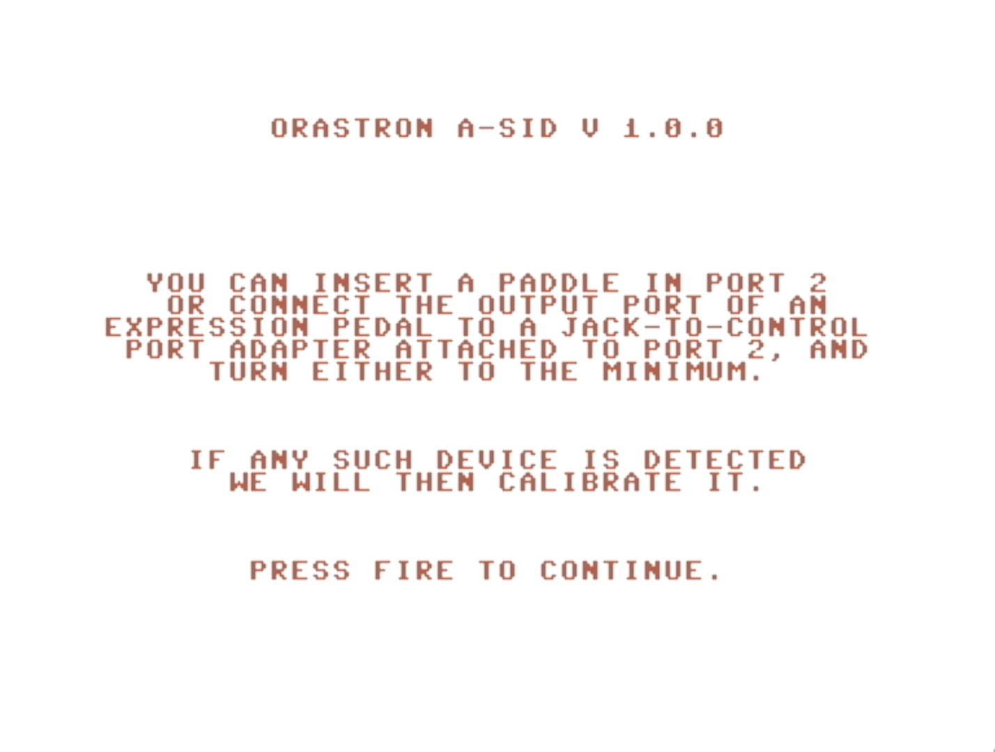
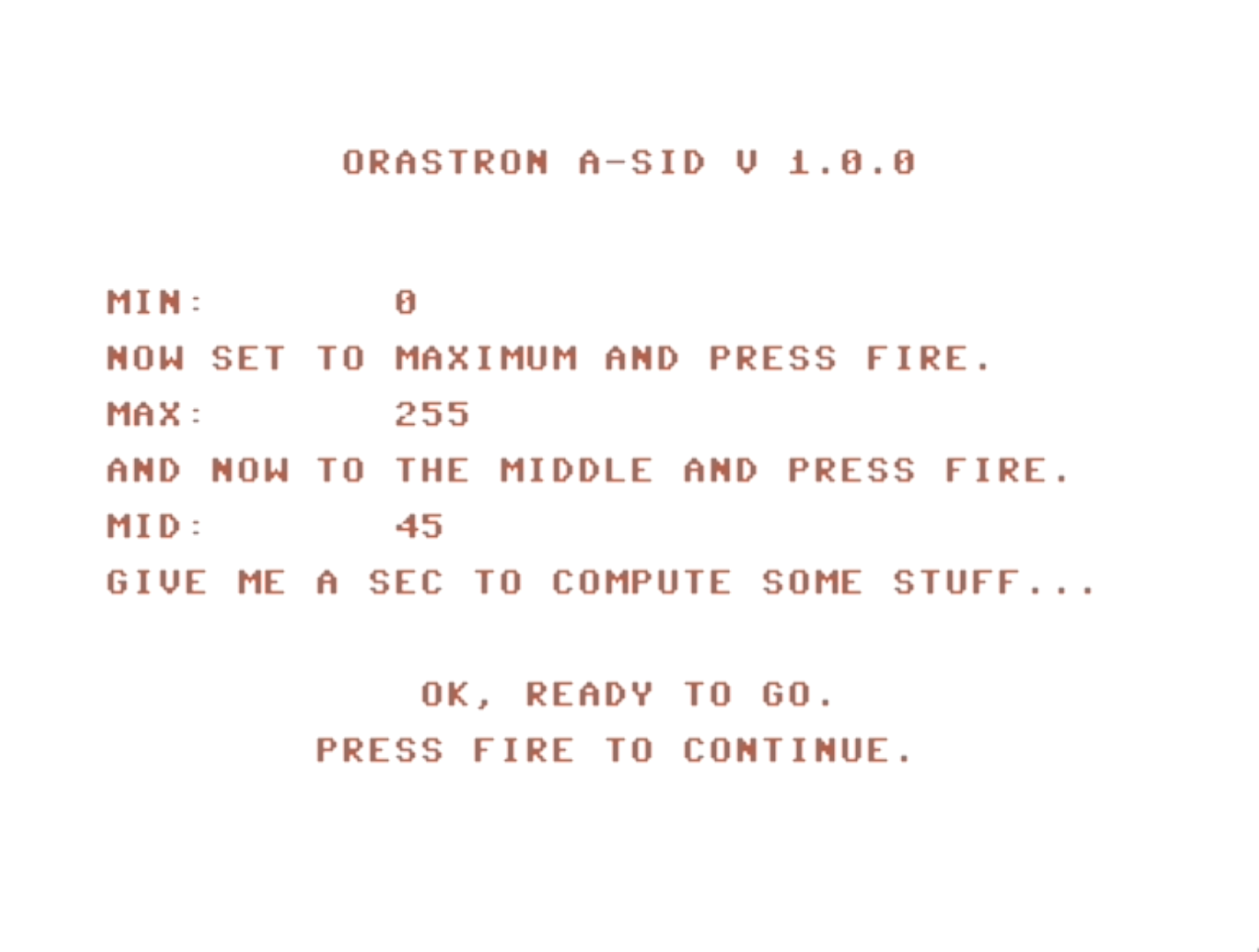
It maps values in the range 0 to 470 kΩ to values in 0 to 255, which is good enough to connect and read the position of expression pedals with sufficiently high resistance (typical ones have maximum 10 kΩ but you can find some on the market with maximum 100 kΩ resistance). In order to artifically cover the full 0-255 range, the program offers a calibration procedure on start. First it asks to "connect the pedal through the adapter" (more on this later) if the user has one and set it to minimum, which also serves as a way to detect its presence (if there's one, the read value will be low, otherwise it will be high). Then, if present, it asks to set it to maximum and middle position, so that it could accomodate those showing nonlinear resistance mapping w.r.t. position (if there are any, this is perhaps more theoretical than real).
Here are the obligatory screenshots for the calibration procedure.
Finally, I had to squeeze my brain a bit to find a way in which the joystick and expression pedal controls could coexist peacefully. In the end I chose to make the expression pedal behave as an extra source of (bipolar) modulation for the cutoff parameter.